Leaf-Spine (Spine-Leaf) Architecture Explained
Start with one server-to-server journey. In 5 minutes, understand the layout; in 10, understand traffic and failures; in 15, understand sizing and oversubscription. The advanced section then explains L3 fabrics, VXLAN, and EVPN.
In This Lesson
Follow a packet across a leaf-spine fabric before learning the design vocabulary. Then connect equal-cost paths, failure behavior, scale, and overlays to real data center decisions.
Quick Learning Map
Keep these three decisions in view as you work through the detailed lesson.
Enter through a leaf
Servers and services attach to leaf switches at the access edge.
Cross one spine
Traffic between leaves takes a predictable leaf-spine-leaf path.
Scale without redesign
Add leaves for ports or spines for fabric capacity and path diversity.
Leaf-Spine (Spine-Leaf) Architecture Explained at a Glance
Use this summary to establish the big picture before moving into commands, examples, and troubleshooting.
Traffic pattern
Every leaf reaches every spine, keeping east-west paths predictable.
Resilience
Multiple equal-cost paths reduce dependence on any single spine.
Modern extension
VXLAN and EVPN can add scalable Layer 2 and Layer 3 overlays.
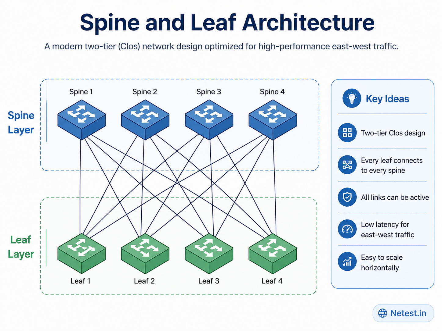
What is spine and leaf architecture?
Leaf-spine is a simple two-layer data-center network. Servers plug into leaf switches. Leaf switches plug into spine switches. To reach a server in another rack, traffic goes up to one spine and down to the other leaf.
Leaf = where things connect
Servers, storage, firewalls, and load balancers normally attach here.
Spine = how racks reach each other
Spines move traffic between leaf switches. They do not normally connect directly to servers.
One design rule
Every leaf has a link to every spine. That gives each rack the same set of paths.
Start here: how does Server A reach Server B?
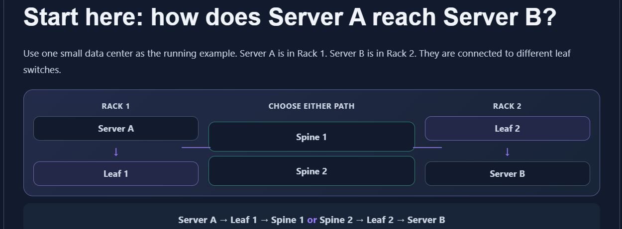
That is the whole architectural idea. A packet first reaches its local leaf, crosses one spine, and arrives at the destination leaf. If both servers connect to the same leaf, the traffic stays on that leaf instead.
Next: why are there two spines?
Leaf 1 has two equally good routes to Leaf 2: one through Spine 1 and one through Spine 2. The switch can use either route. The technical name for choosing among equal routes is ECMP (Equal-Cost Multi-Path).
- Server A sends traffic to Leaf 1.
- Leaf 1 selects Spine 1 or Spine 2 for that flow.
- The selected spine forwards to Leaf 2.
- Leaf 2 delivers the traffic to Server B.
One very large conversation normally stays on one selected path. The benefit appears when the fabric carries many server-to-server flows at the same time.
Then: what happens when a spine fails?
Suppose Spine 1 goes down. Leaf 1 still has its connection through Spine 2, so it uses the remaining path to Leaf 2.
Server A → Leaf 1 → Spine 2 → Leaf 2 → Server B
The fabric has less total capacity during the failure, but communication can continue. This is the practical redundancy benefit of leaf-spine; it is not just a diagram with extra links.
Then: how does the fabric grow?
Need more servers?
Add another leaf switch for another rack, then connect that leaf to every existing spine.
Need more fabric capacity?
Add another spine switch, then connect every existing leaf to it.
Only now is it useful to introduce oversubscription: it compares the bandwidth facing servers with the bandwidth from a leaf into the fabric. It helps answer whether a busy rack has enough uplink capacity.
Why do companies use leaf-spine?
Data centers carry a great deal of east-west traffic: server-to-server traffic inside the building. Leaf-spine keeps those paths short and repeatable.
Predictable traffic path
Servers in different racks usually use leaf → spine → leaf, rather than climbing through several network layers.
Resilience
Multiple spines give a leaf another path when a link or spine fails.
Repeatable growth
Add leaf switches for ports and spine switches for fabric bandwidth without redesigning every rack.
Advanced section
How modern leaf-spine fabrics use L3, VXLAN, and EVPN
You now have the base picture: servers connect to leaves, traffic crosses a spine, and multiple spines provide paths and resilience. The terms below describe how larger modern fabrics implement that same picture.
1. L3 leaf-spine
Modern fabrics commonly route traffic between leaves and spines. Routing keeps all fabric links active and supplies the equal paths that ECMP uses.
2. VXLAN
Imagine Server A and Server B need to stay in the same VLAN even though they sit on different leaves. VXLAN lets that Layer-2 network travel across the routed Layer-3 fabric.
3. EVPN
EVPN tells leaf switches where endpoints such as Server A are located, so VXLAN traffic can be sent to the right leaf.
Scaling and oversubscription
A leaf-spine fabric scales horizontally. More leaf switches give more server-facing ports. More spine switches give more east-west fabric paths and capacity between leaves. The clean mental model is simple: each leaf must connect to each spine.
| Capacity question | Quick design check |
|---|---|
| How many leaf switches can the fabric support? | A spine needs one downlink port for every leaf. If each spine has 32 fabric-facing ports, a full mesh can support up to 32 leaf switches. |
| How many spine switches can a leaf support? | A leaf needs one uplink per spine. Four spines require four uplinks from every leaf. |
| What is oversubscription? | The ratio between server-facing bandwidth and uplink bandwidth. A 48-port 25G leaf with four 100G uplinks has 1200G down and 400G up, or 3:1 oversubscription. |
A practical 4-leaf, 4-spine sizing example
Assume four racks, each with a leaf that has 48 × 25G server ports and four 100G uplinks, one to each spine. Per leaf, the downlink capacity is 48 × 25G = 1.2 Tbps. Fabric capacity is 4 × 100G = 400 Gbps, so the leaf oversubscription ratio is 1200 ÷ 400 = 3:1.
If one spine fails, each leaf retains 300 Gbps of uplink capacity. The new ratio is 1200 ÷ 300 = 4:1. For a server-to-server flow between different leaves, a normal path is Server A → Leaf-1 → Spine-2 → Leaf-4 → Server B. When Spine-2 fails, routing withdraws that path and ECMP rehashes affected flows over the remaining spines; the fabric loses capacity but should not blackhole traffic.
How ECMP actually uses multiple spine paths
ECMP provides aggregate fabric bandwidth across multiple traffic flows. A switch typically hashes a flow using fields such as source IP, destination IP, protocol, and Layer 4 ports, then keeps that flow on the selected path.
Practical commands and verification examples
These are Cisco NX-OS examples; syntax differs on other platforms. The useful part is knowing what healthy output should show and what would indicate a fault.
| Command | Healthy result | Investigate when |
|---|---|---|
show ip ospf neighbor | Every expected spine neighbor is FULL. | A neighbor is missing, stuck in an intermediate state, or flapping. |
show ip route <remote-VTEP> | Multiple equal-cost next hops appear when multiple spine paths are available. | Only one path exists or next hops disappear after a link failure. |
show bgp l2vpn evpn summary | Required EVPN peers are established. | Peers are idle, active, or repeatedly resetting. |
show nve peers | Remote VTEPs are Up. | A remote VTEP is down or absent. |
show nve vni | Required VNIs are Up. | A VNI is down or missing from the expected VTEP. |
show interfaces counters errors | CRC, FEC, and drop counters do not increase. | Counters rise, often pointing to optics, cabling, speed, or FEC issues. |
show interfaces status
show interfaces counters errors
show lldp neighbors
show ip ospf neighbor
show ip route <remote-VTEP>
show ip cef exact-route 10.1.1.10 10.2.2.20
show bgp l2vpn evpn summary
show nve peers
show nve vni
show mac address-table dynamic
show arp
show interface mtu
For a routed underlay, every leaf should have healthy routing adjacencies to every spine. For VXLAN EVPN, each VTEP should have stable EVPN control-plane sessions and correct VNI membership.
Troubleshooting checks
- Confirm every leaf has physical links to every spine and the cabling matches the intended port map.
- Verify interface speed, duplex, FEC, optics, MTU, and error counters on fabric links.
- Check that routed underlay adjacencies are established and stable.
- Confirm equal-cost routes exist where ECMP should be used.
- Validate overlay MTU before troubleshooting application drops.
- Check VXLAN VNI, VLAN-to-VNI mapping, route targets, and VTEP reachability.
- Compare traffic hashing behavior if one uplink is congested while others are quiet.
- Test a spine failure and a leaf uplink failure; traffic should degrade predictably instead of blackholing.
Compute leaf, border leaf, and service leaf roles
Not every leaf has to perform the same job. Separating edge roles helps keep ordinary server traffic from taking unnecessary detours through external services.
Compute leaf
Connects servers, hypervisors, and storage. It is the usual attachment point for workloads and may also act as a VTEP.
Border leaf
Connects the fabric to WAN, internet, data-center interconnect, or external routed networks. It handles north-south connectivity.
Service leaf
Connects firewalls, load balancers, and other service-insertion devices. Placement should avoid needless hairpinning.
Internet / WAN
      |
   Firewall
      |
Border / Service Leaf
       /         \
    Spine       Spine
      |           |
Compute Leaf  Compute Leaf
      |           |
   Servers     Servers
Common leaf-spine design mistakes
- Partial leaf-to-spine mesh: creates uneven ECMP paths and unequal capacity.
- Incorrect MTU: VXLAN traffic can fail even when underlay routing looks healthy.
- Too much oversubscription: east-west bursts can cause drops when uplinks are undersized.
- VLAN-to-VNI mismatch: EVPN sessions may be healthy while workload connectivity is broken.
- Bad service-leaf placement: firewall or load-balancer hairpinning increases latency and burns fabric capacity.
- Assuming ECMP guarantees equal use: hash behavior can leave elephant flows imbalanced.
- Oversized Layer 2 failure domain: broadcast, MAC, and mobility issues affect more workloads.
Spine-leaf advantages and disadvantages
Spine-leaf keeps the fabric simple: leaves connect endpoints, spines move traffic between leaves, and all leaf-to-spine links can be part of the forwarding design. That makes the network easier to scale, but it also means cabling and port planning matter from day one.
Advantages
- Better redundancy: each leaf has paths to multiple spines. If one spine fails, traffic can use the remaining spines instead of losing the leaf completely.
- More usable bandwidth: routed fabrics can use ECMP so several uplinks carry traffic at the same time. In Layer 2 fabrics, technologies such as TRILL or SPB can also avoid the old STP blocked-link problem.
- Easier horizontal growth: need more server ports? Add leaves. Need more fabric capacity? Add spines and connect each leaf to them.
- Lower hardware cost in many builds: fixed switches can work well because spine switches mostly provide fabric ports, while leaf switches handle endpoint attachment.
- Shorter, steadier paths: traffic between servers on different leaves usually follows leaf to spine to leaf, so delay is easier to estimate.
- Better power profile: a design based on fixed switches can use less power per port than a chassis-heavy data center design.
Disadvantages
- Lots of cabling: the full-mesh rule means every leaf needs a link to every spine, so cable count rises quickly as you add devices.
- Port count limits the fabric: spine port count decides how many leaves you can attach. For example, a 32-port spine can connect to 32 leaves if one port is used per leaf.
- Planning is less forgiving: uplink counts, optics, breakout ports, rack locations, and oversubscription targets should be clear before expansion starts.
- Overlays add another layer: if you need the same VLAN across racks over a routed fabric, VXLAN EVPN brings extra control-plane, MTU, and visibility work.
- Shared services need careful placement: firewalls, load balancers, and border links should be placed so traffic does not take an unnecessary detour.
Best fit
Virtualized data centers, private cloud, storage-heavy environments, container platforms, high east-west traffic, and fabrics that need repeatable scaling.
Spine and Leaf Architecture Frequently Asked Questions
What is spine and leaf architecture?
It is a two-tier data center topology where every leaf switch connects to every spine switch for predictable paths and horizontal scaling.
Why does every leaf connect to every spine?
The full mesh keeps bandwidth and path choices consistent. Missing links create uneven ECMP behavior and can overload specific paths.
Is spine-leaf only for Layer 3 networks?
No. Spine-leaf can be L2 or L3, but modern designs commonly use an L3 underlay with VXLAN EVPN when L2 extension is needed.
What is east-west traffic?
East-west traffic is server-to-server or workload-to-workload traffic inside the data center, rather than client-to-server traffic entering or leaving the site.
Where do firewalls fit in a spine-leaf design?
Firewalls usually connect at leaf switches as service nodes or border/service leaf pairs. The right placement depends on whether traffic is north-south, east-west, tenant-to-tenant, or internet-facing.
How is spine-leaf different from three-tier architecture?
Three-tier architecture uses access, distribution, and core layers. Spine-leaf reduces the data center fabric to leaf and spine layers, improving path predictability for east-west traffic.
Related study
Continue with internal Netest.in guides that reinforce the control plane, overlay, and resilient switching topics used in a modern fabric.