Single-Area OSPF Configuration Lab
This lab configures OSPF Area 0 on three Cisco routers connected in a triangle. You will first assign interface IP addresses, then enable OSPF with router IDs and wildcard-mask network statements.
Single-Area OSPF Configuration Lab: Quick Summary
All three routers participate in OSPF process 1 and belong to Area 0. The links are simple /24 Ethernet networks: R1-R2 uses 192.168.12.0/24, R1-R3 uses 192.168.13.0/24, and R2-R3 uses 192.168.23.0/24.
Single-Area OSPF Configuration Lab: Table of Contents
1. Topology and Addressing
The topology uses three point-to-point style Ethernet links. Each router has two active interfaces, and every link is advertised into OSPF Area 0.
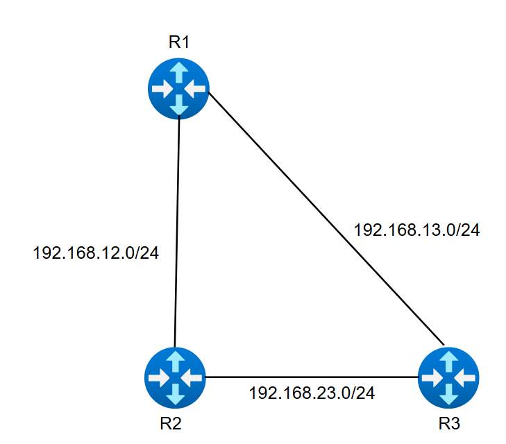
| Link | Network | Router Interface | IP Address |
|---|---|---|---|
| R1 to R2 | 192.168.12.0/24 | R1 Ethernet0/1 R2 Ethernet0/1 |
192.168.12.1 192.168.12.2 |
| R1 to R3 | 192.168.13.0/24 | R1 Ethernet0/2 R3 Ethernet0/1 |
192.168.13.1 192.168.13.3 |
| R2 to R3 | 192.168.23.0/24 | R2 Ethernet0/2 R3 Ethernet0/2 |
192.168.23.2 192.168.23.3 |
2. Base Interface Configuration
Start by configuring hostnames, interface IP addresses and enabling the router interfaces with no shutdown. This step only builds IP connectivity; OSPF is added in the next section.
R1 Configuration
hostname R1
!
interface Ethernet0/1
 ip address 192.168.12.1 255.255.255.0
 no shutdown
!
interface Ethernet0/2
 ip address 192.168.13.1 255.255.255.0
 no shutdown
!
end
R2 Configuration
hostname R2
!
interface Ethernet0/1
 ip address 192.168.12.2 255.255.255.0
 no shutdown
!
interface Ethernet0/2
 ip address 192.168.23.2 255.255.255.0
 no shutdown
!
end
R3 Configuration
hostname R3
!
interface Ethernet0/1
 ip address 192.168.13.3 255.255.255.0
 no shutdown
!
interface Ethernet0/2
 ip address 192.168.23.3 255.255.255.0
 no shutdown
!
endshow ip interface brief and simple pings between neighboring routers.
3. OSPF Area 0 Configuration
Enable OSPF with router ospf 1, set a stable router ID, and advertise each connected /24 network into Area 0 using a wildcard mask.
R1 OSPF
configure terminal
router ospf 1
 router-id 1.1.1.1
 network 192.168.12.0 0.0.0.255 area 0
 network 192.168.13.0 0.0.0.255 area 0
end
R2 OSPF
configure terminal
router ospf 1
 router-id 2.2.2.2
 network 192.168.12.0 0.0.0.255 area 0
 network 192.168.23.0 0.0.0.255 area 0
end
R3 OSPF
configure terminal
router ospf 1
 router-id 3.3.3.3
 network 192.168.13.0 0.0.0.255 area 0
 network 192.168.23.0 0.0.0.255 area 0
end- Process ID: The value
1is locally significant. It does not need to match between routers, but keeping it consistent makes the lab easier to read. - Router ID: Manually setting router IDs keeps neighbor tables predictable: R1 is 1.1.1.1, R2 is 2.2.2.2 and R3 is 3.3.3.3.
- Area: All networks are in Area 0, so this is a single-area OSPF design.
4. How the Network Command Works
The OSPF network statement selects local interfaces that match the address and wildcard mask, then advertises those connected networks into the chosen OSPF area.
| Command Part | Meaning | Example |
|---|---|---|
network 192.168.12.0 |
Matches the R1-R2 subnet. | R1 Ethernet0/1 and R2 Ethernet0/1 |
0.0.0.255 |
Wildcard mask for a /24 subnet. It is the inverse of 255.255.255.0. | Match all addresses from .0 through .255 |
area 0 |
Places the matched interface into OSPF Area 0. | Backbone/single-area lab |
5. Verification Commands
After the OSPF commands are applied, each router should form two neighbor adjacencies because every router connects to the other two routers in the triangle.
show ip ospf neighbor
Confirms neighbor IDs, adjacency state, dead timer, neighbor address and interface. The expected state is FULL.
show ip protocols
Confirms OSPF process 1, router ID, networks advertised and administrative distance 110.
show ip route ospf
Shows routes learned through OSPF. R1 should learn 192.168.23.0/24, R2 should learn 192.168.13.0/24, and R3 should learn 192.168.12.0/24.
show ip ospf interface brief
Lists OSPF-enabled interfaces, process ID, area, cost and neighbor count in a compact format.
Expected Neighbor Result
R1#show ip ospf neighbor

Neighbor ID     State           Address         Interface
2.2.2.2         FULL            192.168.12.2    Ethernet0/1
3.3.3.3         FULL            192.168.13.3    Ethernet0/2
6. Troubleshooting Checklist
If a neighbor does not reach FULL state, check the basics before changing the routing design.
- Interfaces: Confirm every Ethernet interface is up/up with
show ip interface brief. - IP addressing: Make sure both sides of each link are in the same /24 subnet.
- Wildcard masks: Use
0.0.0.255for these /24 networks, not255.255.255.0. - Timers and area: OSPF neighbors must agree on area ID, hello/dead timers, authentication and network type.
- Router IDs: Router IDs must be unique. If you change a router ID after OSPF starts, clear the process or reload the router.