Packet Tracer 8.1.1 Tutorial: IP Telephony & VoIP Basic Configuration
This Packet Tracer 8.1.1 tutorial shows how to set up basic IP telephony and voice over IP (VoIP) in a lab network. You will configure Call Manager Express (CME) on a Cisco 2811 ISR router, use DHCP for Cisco IP phones, set a voice VLAN on a switch, assign phone numbers with ephone-dn, and place a test call between two IP phones.
In This Lesson
Build a two-phone Cisco Packet Tracer voice lab from addressing to a completed call. Each configuration task includes the dependency that makes the next stage possible.
Quick Learning Map
Keep this three-step view in mind as you work through the detailed lesson.
Prepare data and voice access
Configure router addressing, DHCP, switch ports, and the voice VLAN.
Create telephony service
Define Call Manager Express, extensions, and phone assignments.
Register and test
Verify phone addresses and extensions, then place a call in both directions.
Packet Tracer 8.1.1 Tutorial: IP Telephony & VoIP Basic Configuration at a Glance
Use this summary before moving into the detailed explanations, examples, commands, and checks.
Core focus
Build a two-phone Cisco Packet Tracer voice lab from addressing to a completed call.
Key connection
Prepare data and voice access → Create telephony service → Register and test
Practical outcome
Each configuration task includes the dependency that makes the next stage possible.
Packet Tracer 8.1.1 Tutorial: IP Telephony & VoIP: Quick Summary
Packet Tracer 8.1.1 includes VoIP features so you can practice IP telephony without real hardware. In this lab, RouterA (2811) acts as the Call Manager Express server and DHCP server. IP phones get an IP address and learn where the TFTP server is (DHCP option 150). The switch carries voice traffic on a voice VLAN. After you assign directory numbers, two Cisco IP phones can register and call each other.
1. What This Lab Covers
This tutorial is for anyone learning Cisco IP telephony, VoIP basics, or Packet Tracer voice labs. It uses simple steps and real IOS-style commands you can copy into Packet Tracer 8.1.1.
By the end, you will know how to:
- Configure Call Manager Express (CME) on a Cisco 2811 ISR router.
- Use telephony devices in Packet Tracer (Cisco IP phones and an analog phone).
- Understand dial peers in context (this lab uses CME directory numbers instead of full dial-peer routing).
- Connect and register Cisco IP phones and work with an analog phone on the same voice network.
- Build a small VoIP lab with DHCP, TFTP (option 150), and a voice VLAN.
2. Network Diagram
The lab topology includes RouterA (2811 with CME), SwitchA, IP Phone 1, IP Phone 2, and optional analog phone equipment as shown in your Packet Tracer file.
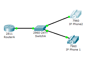
VoIP lab topology — RouterA, SwitchA, and IP telephony devices
3. Before You Start
Follow these rules so the lab works the first time:
- Connect only IP Phone 1 at the start. Leave IP Phone 2 disconnected until Task 6.
- Power on devices and wait a few seconds after each major config change.
- Hover over an IP phone in Packet Tracer to see its IP address, TFTP server, and extension number.
4. Task 1: Configure FastEthernet 0/0 and DHCP on RouterA
RouterA needs a LAN interface for voice devices and a DHCP pool so each Cisco IP phone gets an IP address and the TFTP server location.
Step A — Set the LAN interface
Use 192.168.10.1/24 on FastEthernet 0/0. Do not forget no shutdown.
RouterA — Interface and DHCP
RouterA>enable
RouterA#configure terminal
RouterA(config)#interface FastEthernet0/0
RouterA(config-if)#ip address 192.168.10.1 255.255.255.0
RouterA(config-if)#no shutdown
Step B — Create the VOICE DHCP pool
The DHCP server gives phones an IP, a default gateway, and option 150 (TFTP server IP). Option 150 is required for VoIP and IP telephony in Cisco labs.
RouterA(config)#ip dhcp pool VOICE
RouterA(dhcp-config)#network 192.168.10.0 255.255.255.0
RouterA(dhcp-config)#default-router 192.168.10.1
RouterA(dhcp-config)#option 150 ip 192.168.10.15. Task 2: Configure Call Manager Express on RouterA
Call Manager Express (CME) turns the 2811 router into a small IP PBX for Packet Tracer. The telephony-service block enables VoIP on the network.
RouterA — telephony-service
RouterA(config)#telephony-service
RouterA(config-telephony)#max-dn 5
RouterA(config-telephony)#max-ephones 5
RouterA(config-telephony)#ip source-address 192.168.10.1 port 2000
RouterA(config-telephony)#auto assign 4 to 6
RouterA(config-telephony)#auto assign 1 to 5- max-dn — maximum directory numbers (extensions).
- max-ephones — maximum IP phones that can register.
- ip source-address — IP and port phones use to register to CME.
- auto assign — maps line buttons to extension numbers automatically.
6. Task 3: Configure Voice VLAN on SwitchA
A voice VLAN separates voice traffic from data traffic on the switch. Data stays on the access VLAN; voice uses the voice VLAN you define.
SwitchA — access and voice VLAN
SwitchA(config)#interface range fa0/1 - 5
SwitchA(config-if-range)#switchport mode access
SwitchA(config-if-range)#switchport voice vlan 1
In Packet Tracer, voice VLAN 1 matches the lab design. On real networks you often use a dedicated voice VLAN ID (for example VLAN 150).
7. Task 4: Phone Directory for IP Phone 1
IP Phone 1 is on SwitchA, but it still needs a directory number (extension) from CME. Use ephone-dn to assign the phone number.
RouterA — extension 54001
RouterA(config)#ephone-dn 1
RouterA(config-ephone-dn)#number 54001
This is how CME links a logical line to extension 54001. Dial peers on larger VoIP networks route calls between sites; in this CME lab, directory numbers are enough for phone-to-phone calling.
8. Task 5: Verify IP Phone 1
Give the phone a short time to register. Then confirm:
- IP Phone 1 has a DHCP IP address on 192.168.10.0/24.
- Extension 54001 appears on the phone display or in the hover summary.
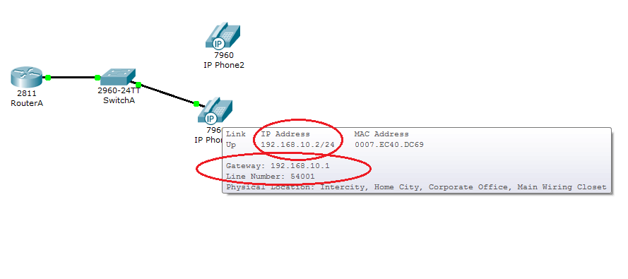
IP Phone 1 — configured with IP address and phone number 54001 (front view)
9. Task 6: Phone Directory for IP Phone 2
Now connect IP Phone 2 to SwitchA. In the Physical tab, attach the power adapter and turn the phone on.
RouterA — extension 54002
RouterA(config)#ephone-dn 2
RouterA(config-ephone-dn)#number 54002
10. Task 7: Verify IP Phone 2 and Test a Call
Use the same checks as Task 5 for IP Phone 2:
- Valid IP address from DHCP.
- Extension 54002 assigned by RouterA CME.
From IP Phone 2, dial 54001 and confirm IP Phone 1 rings and can answer. This proves your VoIP, CME, and IP telephony setup works end to end.
Packet Tracer 8.1.1 Tutorial: IP Telephony & VoIP: Tags and Keywords
Packet Tracer 8.1.1, Packet Tracer VoIP tutorial, IP telephony tutorial, voice over IP lab, Cisco Packet Tracer lab, Call Manager Express, CME configuration, Cisco 2811 router voice, ISR voice configuration, Cisco IP phone Packet Tracer, analog phone Packet Tracer, telephony-service, ephone-dn, max-dn, max-ephones, DHCP option 150, TFTP server IP phone, voice VLAN, switchport voice vlan, dial peer, VoIP lab CCNA, CCNA voice lab, Cisco unified communications lab, basic VoIP setup, Packet Tracer IP telephony, IP phone registration, extension 54001, extension 54002, networking lab tutorial.