Rapid Spanning Tree Configuration
Configure Cisco Rapid PVST+, follow the proposal-agreement handshake, and see how RSTP restores a loop-free path quickly.
Spanning Tree Protocol Series
Follow these lessons in order to move from Layer 2 loop prevention through edge-port protection to Rapid PVST+ configuration.
In This Lesson
Understand why Rapid STP converges faster before entering commands. Port roles, proposal and agreement, edge behavior, and failure testing are connected into one workflow.
Quick Learning Map
Keep these three decisions in view as you work through the detailed lesson.
Establish roles
Elect the root and identify root, designated, alternate, and backup ports.
Synchronize quickly
Proposal and agreement let point-to-point links transition safely.
Test a failure
Observe alternate-path activation and confirm traffic recovers as expected.
Rapid Spanning Tree Configuration at a Glance
Use this summary to establish the big picture before moving into commands, examples, and troubleshooting.
Standard
RSTP is IEEE 802.1w; Rapid PVST+ applies it per VLAN on Cisco switches.
States
Discarding, learning, and forwarding replace the five classic STP states.
Speed
Explicit handshakes and alternate ports reduce dependence on long timers.
What is Rapid Spanning Tree?
Enable Rapid PVST+ on Cisco switches
Configure the mode consistently on every switch in the Layer 2 domain. The command changes the spanning-tree mode globally.
SW1(config)# spanning-tree mode rapid-pvst
SW2(config)# spanning-tree mode rapid-pvst
SW3(config)# spanning-tree mode rapid-pvst
Rapid PVST+ calculates a separate rapid spanning tree per VLAN. Root placement should therefore be planned and verified per VLAN.
SW1# show spanning-tree summary
Switch is in rapid-pvst mode

SW1# show spanning-tree vlan 10
VLAN0010
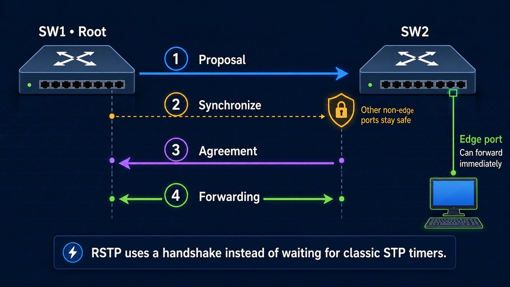
Spanning tree enabled protocol rstpRSTP synchronization: proposal and agreement
On an eligible point-to-point link, RSTP can establish a safe forwarding relationship without waiting through the classic listening and learning timers.
SW1# debug spanning-tree events
RSTP(10): transmitting a proposal on Fa0/14

SW2#
RSTP(10): received superior bpdu on Fa0/14
RSTP(10): Fa0/14 is now root port
RSTP(10): syncing port Fa0/16
RSTP(10): transmitting an agreement on Fa0/14

SW1#
RSTP(10): received an agreement on Fa0/14
undebug all.Rapid PVST+ topology and port roles
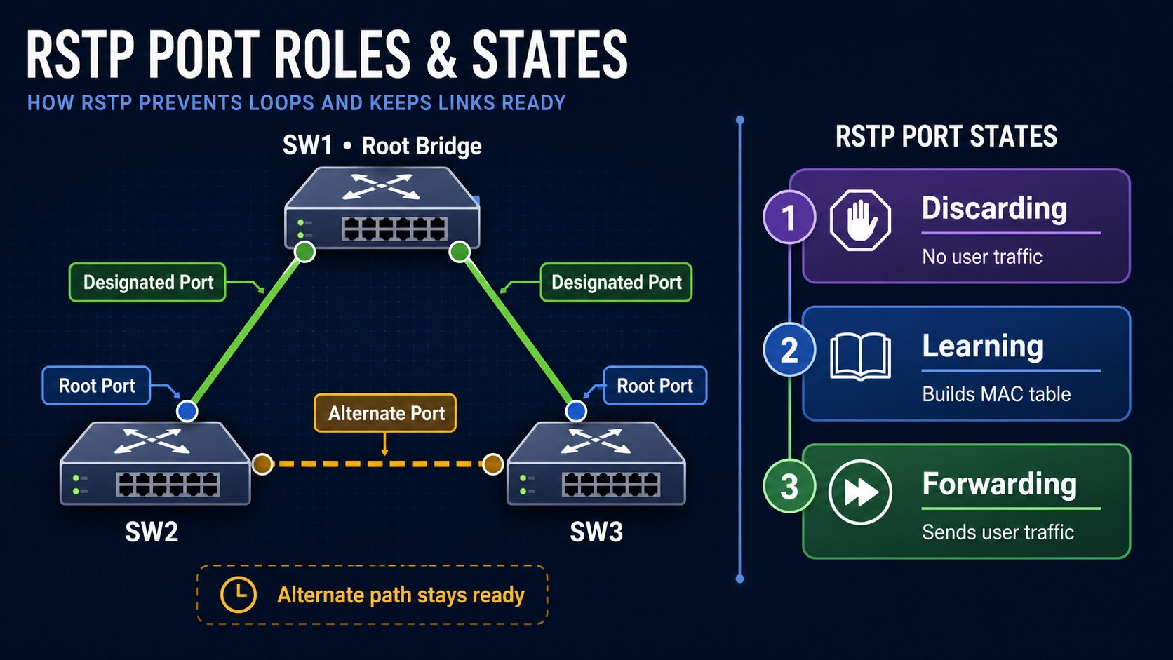
The steady-state tree can look identical to classic STP. The difference is how quickly RSTP reaches and repairs that topology.
Root port
Best path from a non-root switch toward the root bridge.
Designated port
Best port forwarding from a segment toward the root.
Alternate port
Backup path toward the root; normally discarding.
Backup port
Backup for the same shared segment; uncommon today.
RSTP port states
RSTP reduces the five classic 802.1D states to three operational states.
| Classic STP state | RSTP state | Learns MAC addresses? | Forwards user frames? |
|---|---|---|---|
| Disabled | Discarding | No | No |
| Blocking | Discarding | No | No |
| Listening | Discarding | No | No |
| Learning | Learning | Yes | No |
| Forwarding | Forwarding | Yes | Yes |
Port role and port state are separate. For example, a designated port can temporarily be discarding while synchronization is in progress.
RSTP BPDUs and link types
Unlike classic STP, every RSTP bridge originates BPDUs at the hello interval. Rapid BPDUs also carry proposal, agreement, role and state information in the flags.
Normally inferred from full duplex. Eligible for proposal-agreement rapid transition.
Normally inferred from half duplex, such as a legacy hub. Rapid handshake behavior is limited.
SW2# show spanning-tree vlan 10
Interface  Role Sts Cost  Prio.Nbr Type
---------  ---- --- ----- -------- ----------------
Fa0/14     Root FWD 19    128.14   P2p
Fa0/16     Altn BLK 19    128.16   P2p

SW2# debug spanning-tree bpdu
The Type column is a fast way to confirm point-to-point, shared, edge, or legacy-peer behavior.
How RSTP handles link failures
SW3 immediately recognizes the local link failure and can promote its alternate port as the new root port.
Fresh BPDUs and the rapid role-selection process correct the topology without optional legacy BackboneFast configuration.
SW3#
RSTP(10): root port Fa0/14 is going down
RSTP(10): Fa0/16 is now root port
How RSTP handles topology changes
RSTP treats a non-edge port moving to forwarding as a topology change. The switch sets the topology-change flag in its BPDUs, and receiving switches rapidly age affected dynamic MAC entries so traffic can follow the new path.
A link failure by itself is not the trigger, and edge-port changes are excluded. This prevents an ordinary endpoint disconnect from causing unnecessary network-wide MAC relearning.
Configure endpoint-facing RSTP edge ports
An endpoint does not participate in proposal-agreement negotiation. Mark a verified host-facing access port as an edge port with PortFast so it forwards immediately.
SW2(config)# interface FastEthernet0/2
SW2(config-if)# switchport mode access
SW2(config-if)# spanning-tree portfast
SW2(config-if)# spanning-tree bpduguard enable
On newer platforms, explicit edge syntax may also be available:
SW2(config-if)# spanning-tree portfast edge
For a complete edge-port lesson, read Cisco PortFast Configuration.
Rapid PVST+ compatibility with classic STP
RSTP can interoperate with a neighbor running legacy IEEE 802.1D behavior. The rapid switch detects the legacy BPDU and operates with classic behavior on that port.
SW2(config)# spanning-tree mode pvst

SW1# show spanning-tree vlan 10
Interface  Role Sts Cost  Prio.Nbr Type
---------  ---- --- ----- -------- ----------------
Fa0/14     Desg FWD 19    128.14   P2p Peer(STP)
The topology remains loop-free, but the legacy boundary cannot use the complete proposal-agreement process. Treat compatibility as a migration feature, not a reason to leave an unplanned mixed-mode design.
Rapid spanning tree verification checklist
- Confirm every intended switch reports
rapid-pvstmode. - Verify the expected root bridge for every active VLAN.
- Check root, designated, alternate and any unexpected backup roles.
- Confirm inter-switch links show the intended
P2ptype. - Verify endpoint ports show edge behavior and BPDU Guard protection.
- Look for
Peer(STP)boundaries during migration. - Test failover during a controlled window and record convergence results.
show spanning-tree summary
show spanning-tree vlan 10
show spanning-tree vlan 10 detail
show spanning-tree interface GigabitEthernet1/0/1 detail
show interfaces status err-disabled
Common Rapid PVST+ mistakes
- Changing only one switch: mixed operation works, but legacy boundaries lose rapid behavior.
- Confusing role with state: root/designated/alternate/backup are roles; discarding/learning/forwarding are states.
- Assuming every full-duplex link is safe: point-to-point classification enables negotiation but does not correct a bad physical design.
- Forgetting per-VLAN roots: Rapid PVST+ maintains an instance and root election per VLAN.
- Using PortFast on switch links: edge configuration can allow an immediate loop.
- Running debug commands in production without controls: use show commands first.
Rapid Spanning Tree FAQs
What command enables Rapid PVST+?
Use spanning-tree mode rapid-pvst in global configuration mode on each participating Cisco switch.
Is Rapid PVST+ the same as RSTP?
Rapid PVST+ is Cisco’s per-VLAN implementation of RSTP concepts. It runs a rapid spanning-tree instance for each VLAN.
Does RSTP still use BPDUs?
Yes. Every bridge sends RSTP BPDUs at the hello interval, and flag bits communicate role, state, proposal, agreement and topology-change information.
Why does RSTP converge faster?
It uses explicit alternate paths, direct neighbor failure detection, edge ports, and proposal-agreement negotiation on point-to-point links instead of relying only on classic timers.
What is an RSTP backup port?
It is a redundant port from the same switch to the same shared segment. It is rare in modern full-duplex switched networks.
Can RSTP work with old STP switches?
Yes, but the port connected to the legacy neighbor falls back to classic behavior and cannot provide full rapid convergence across that boundary.
Authoritative references
RSTP roles, states, rapid transitions and compatibility were verified against Cisco’s Understanding Rapid Spanning Tree Protocol and Rapid PVST+ configuration guide.