Private VLAN (PVLAN) Configuration on Cisco IOS
Private VLANs add port-level isolation inside one IP subnet. This practical guide explains primary, community, and isolated VLANs, then builds and verifies a complete Cisco IOS configuration.
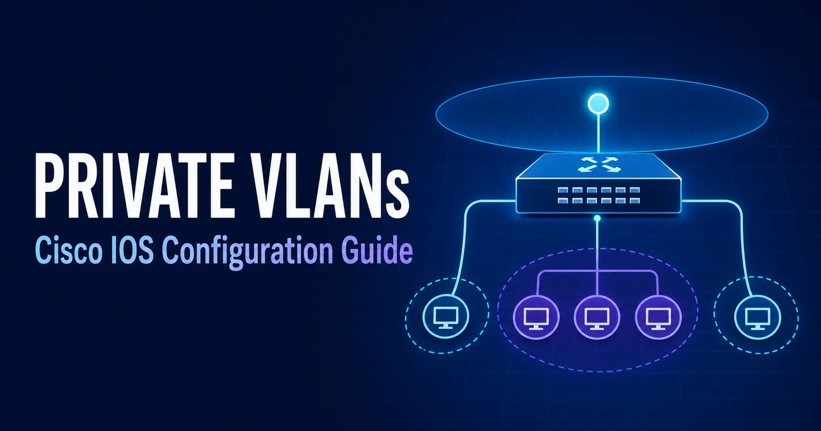
In This Lesson
Use private VLANs to isolate hosts that share an IP subnet and default gateway. You will map primary and secondary VLANs to port roles, configure Cisco IOS, and verify the allowed communication paths.
Quick Learning Map
Keep this three-step view in mind as you work through the detailed lesson.
Model the roles
Define the primary VLAN, isolated or community secondary VLANs, and promiscuous gateway port.
Configure the mappings
Associate VLANs and apply the correct host or promiscuous switchport mode.
Prove isolation
Test the communication matrix and inspect VLAN and interface state before production use.
Private VLAN (PVLAN) Configuration on Cisco IOS at a Glance
Use this summary to establish the big picture before moving into the detailed explanations, commands, and checks.
Core focus
Use private VLANs to isolate hosts that share an IP subnet and default gateway.
Key connection
Model the roles → Configure the mappings → Prove isolation
Practical outcome
You will map primary and secondary VLANs to port roles, configure Cisco IOS, and verify the allowed communication paths.
1. What Is a Private VLAN?
A Private VLAN (PVLAN) is a Layer 2 segmentation feature that restricts direct communication between switch ports without assigning every group a separate IP subnet. A primary VLAN represents the overall broadcast domain, while one or more secondary VLANs define which endpoint ports may communicate.
This design is useful when many devices need the same default gateway but should not trust one another. Instead of consuming a new subnet for every small group, the switch enforces isolation inside the shared subnet.
2. PVLAN VLAN and Port Roles
PVLAN terminology describes both VLAN types and switch-port behavior. Keeping these two ideas separate makes the configuration easier to understand.
Primary VLAN
The parent VLAN for the PVLAN domain. It contains the promiscuous port and is associated with all secondary VLANs.
Community VLAN
Hosts in the same community can communicate with one another and with mapped promiscuous ports.
Isolated VLAN
Hosts cannot communicate directly with other isolated hosts. They can reach only mapped promiscuous ports.
Promiscuous Port
Can exchange frames with every mapped secondary VLAN. It normally faces a router, firewall, gateway, or shared server.
Community Port
Belongs to a community secondary VLAN and can reach peers in that same community plus the promiscuous port.
Isolated Port
Belongs to the isolated secondary VLAN and forwards endpoint traffic only toward the promiscuous port.
3. Traffic Rules and Communication Matrix
The primary VLAN carries downstream traffic from promiscuous ports to mapped hosts. Community and isolated secondary VLANs control upstream and host-to-host forwarding. Normal MAC address learning still occurs, but the PVLAN rules limit which ports can exchange frames.
| Source port | Same community | Different community | Isolated host | Promiscuous port |
|---|---|---|---|---|
| Community host | Allowed | Blocked | Blocked | Allowed |
| Isolated host | Blocked | Blocked | Blocked | Allowed |
| Promiscuous port | Allowed | Allowed | Allowed | Not applicable |
4. Example Topology and Addressing
The configuration below uses one primary VLAN, one community VLAN, and one isolated VLAN. Every endpoint remains in the 192.168.1.0/24 subnet.
Community VLAN 501
Fa0/1
Fa0/2
H1 and H2 can reach each other and the gateway.
Isolated VLAN 502
Fa0/3
Fa0/4
H3 and H4 can reach the gateway, but not each other.
| Purpose | VLAN ID | Type | Interfaces |
|---|---|---|---|
| PVLAN parent | 500 | Primary | Fa0/24 mapping |
| Trusted host group | 501 | Community | Fa0/1–2 |
| Fully separated hosts | 502 | Isolated | Fa0/3–4 |
| Gateway or shared server | 500 mapped to 501 and 502 | Promiscuous | Fa0/24 |
Private VLAN (PVLAN) Configuration on Cisco IOS: 5. Cisco IOS Configuration
Confirm that the switch model and software release support PVLANs before starting. The syntax below follows the classic Cisco IOS pattern used on supported Catalyst platforms.
Step 1: Prepare VTP
On platforms that require it, place VTP in transparent mode so the local switch can create and manage the PVLAN definitions.
SW1# configure terminal
SW1(config)# vtp mode transparent
Step 2: Create the secondary VLANs
Define VLAN 501 as a community VLAN and VLAN 502 as an isolated VLAN.
SW1(config)# vlan 501
SW1(config-vlan)# private-vlan community
SW1(config-vlan)# exit
SW1(config)# vlan 502
SW1(config-vlan)# private-vlan isolated
SW1(config-vlan)# exit
Step 3: Create the primary VLAN and associations
Define VLAN 500 as the primary VLAN, then associate both secondary VLANs with it.
SW1(config)# vlan 500
SW1(config-vlan)# private-vlan primary
SW1(config-vlan)# private-vlan association 501
SW1(config-vlan)# private-vlan association add 502
SW1(config-vlan)# exit
Step 4: Configure community host ports
Fa0/1 and Fa0/2 become PVLAN host ports associated with primary VLAN 500 and community VLAN 501.
SW1(config)# interface range fa0/1 - 2
SW1(config-if-range)# switchport
SW1(config-if-range)# switchport mode private-vlan host
SW1(config-if-range)# switchport private-vlan host-association 500 501
SW1(config-if-range)# spanning-tree portfast
SW1(config-if-range)# exit
Step 5: Configure isolated host ports
Fa0/3 and Fa0/4 use the same host-port mode but are associated with isolated VLAN 502.
SW1(config)# interface range fa0/3 - 4
SW1(config-if-range)# switchport
SW1(config-if-range)# switchport mode private-vlan host
SW1(config-if-range)# switchport private-vlan host-association 500 502
SW1(config-if-range)# spanning-tree portfast
SW1(config-if-range)# exit
Step 6: Configure the promiscuous port
Fa0/24 connects to the gateway or shared server and maps the primary VLAN to both secondary VLANs.
SW1(config)# interface fa0/24
SW1(config-if)# switchport
SW1(config-if)# switchport mode private-vlan promiscuous
SW1(config-if)# switchport private-vlan mapping 500 501
SW1(config-if)# switchport private-vlan mapping 500 add 502
SW1(config-if)# no shutdown
SW1(config-if)# end6. Verification and Testing
Verify the VLAN roles, interface associations, and promiscuous mapping before testing reachability.
Display PVLAN relationships and port membership:
SW1# show vlan private-vlan

Primary  Secondary  Type       Ports
-------  ---------  ---------  -------------------------
500      501        community  Fa0/1, Fa0/2, Fa0/24
500      502        isolated   Fa0/3, Fa0/4, Fa0/24
Confirm each VLAN type:
SW1# show vlan private-vlan type

Vlan  Type
----  ---------
500   primary
501   community
502   isolated
Inspect a host port and the promiscuous port:
SW1# show interfaces fa0/1 switchport
SW1# show interfaces fa0/3 switchport
SW1# show interfaces fa0/24 switchport
Expected reachability
- H1 can ping H2 because both are in community VLAN 501.
- H1 and H2 can ping 192.168.1.254 through the promiscuous port.
- H3 and H4 can each ping 192.168.1.254.
- H3 cannot ping H4 because VLAN 502 is isolated.
- H1 cannot reach H3 or H4 directly because secondary VLANs do not communicate with one another.
- The device on Fa0/24 can initiate traffic to every mapped host, subject to any Layer 3 security policy.
7. PVLANs Across Multiple Switches
Supported Cisco platforms can carry the primary and secondary VLANs across an 802.1Q trunk. Allow VLANs 500, 501, and 502 on the inter-switch trunk, and create matching PVLAN definitions on every participating switch when the control-plane mode does not distribute them.
SW1(config)# interface gi0/1
SW1(config-if)# switchport mode trunk
SW1(config-if)# switchport trunk allowed vlan 500-5028. Common Problems and Troubleshooting
| Symptom | Likely cause | What to check |
|---|---|---|
| Host cannot reach the gateway | Missing host association or promiscuous mapping | Compare the primary-secondary pair on both interfaces. |
| Community peers cannot communicate | Ports are in different secondary VLANs | Run show vlan private-vlan and confirm both ports use VLAN 501. |
| Isolated hosts can communicate | Ports are ordinary access ports or assigned to a community | Confirm private-vlan host mode and association 500 502. |
| Remote-switch PVLAN fails | VLANs are pruned or definitions do not match | Inspect the trunk allow-list and local PVLAN database on both switches. |
| Commands are rejected | Unsupported model, license, image, or configuration mode | Check the exact platform feature guide and software release. |
Useful checks include:
show vlan private-vlan
show vlan private-vlan type
show interfaces switchport
show interfaces trunk
show mac address-table
show running-config interface fa0/24
9. Benefits and Use Cases
PVLANs are most valuable where endpoints share infrastructure but should have limited east-west connectivity.
- Hosting and data centers: isolate tenant or server ports while retaining a shared default gateway.
- Service-provider access: prevent customers on the same Layer 2 segment from communicating directly.
- Guest and dormitory networks: reduce peer-to-peer exposure without allocating a subnet per room or user.
- DMZ server segments: limit direct server-to-server traffic and steer communication through a firewall.
- IP address conservation: apply granular isolation without creating many small VLAN subnets.
PVLANs improve segmentation, but they do not replace firewalls, access control lists, endpoint security, or identity-based policy. Treat them as one Layer 2 control in a broader security design.
Private VLAN (PVLAN) Configuration on Cisco IOS: Frequently Asked Questions
What is a Private VLAN?
A Private VLAN is a Layer 2 segmentation feature that restricts communication between switch ports while keeping their connected devices in the same IP subnet.
Can isolated ports communicate with each other?
No. Isolated ports can communicate only with a mapped promiscuous port, not with other isolated ports.
What does a promiscuous port do?
It communicates with every mapped secondary VLAN and commonly connects the PVLAN to a router, firewall, default gateway, or shared service.
Can a community VLAN reach an isolated VLAN?
Not directly at Layer 2. Communication must pass through a Layer 3 device or policy service connected through a promiscuous port.
Do PVLANs use separate IP subnets?
No. The primary and its associated secondary VLANs normally share one IP subnet, which is one of the main reasons to deploy PVLANs.
Private VLAN (PVLAN) Configuration on Cisco IOS: Tags and Keywords
Private VLAN, PVLAN, Cisco IOS private VLAN, community VLAN, isolated VLAN, promiscuous port, port isolation, private-vlan configuration