802.1Q Tunneling (Q-in-Q) Configuration
Build a five-device Cisco lab that carries customer VLAN 12 across a provider network on VLAN 123, then verify the tunnel and its frame-size requirements.
In This Lesson
Follow the tag from R1 to R2, configure every device, then prove the provider transports only the outer service VLAN.
Workflow: Customer tags → Customer receives
Think of Q-in-Q as an outer transport label wrapped around a customer's original tagged frame.
Customer tags
R1 sends a frame with its VLAN 12 tag.
Provider carries
SW1 adds VLAN 123; provider switches forward using that outer tag.
Customer receives
SW2 removes the outer tag and gives R2 the original VLAN 12 frame.
Q-in-Q Overview
802.1Q tunneling lets a provider transport tagged customer Layer 2 traffic across its own switched network. Its outer service VLAN separates customer services while preserving the inner customer VLAN.
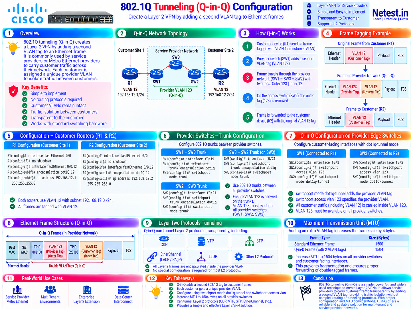
Topology and VLAN Plan
R1 and R2 are customer sites. SW1 and SW2 are provider edge switches, and SW3 is the transit switch. Both routers use VLAN 12 and subnet 192.168.12.0/24; the provider uses VLAN 123 for this service.
| Endpoint | Role | Value |
|---|---|---|
| R1 Fa0/0.12 | Customer site 1 | VLAN 12 · 192.168.12.1/24 |
| R2 Fa0/0.12 | Customer site 2 | VLAN 12 · 192.168.12.2/24 |
| SW1 Fa0/1, SW2 Fa0/2 | Customer-facing tunnel ports | Provider VLAN 123 |
| SW1–SW3–SW2 | Provider trunks | Carry VLAN 123 |
Prerequisites: basic switching, VLANs, and 802.1Q trunking. Interface numbering and command support vary by Cisco model; adapt these lab examples to your hardware or simulator.
How the Two Tags Travel
R1 sends a frame tagged with VLAN 12. SW1 adds VLAN 123 as the outer tag. SW3 and SW2 forward on VLAN 123. At the far tunnel port, SW2 removes the outer tag and delivers the original VLAN 12 frame to R2.
| Location | Tag stack, outer → inner |
|---|---|
| From R1 | 12 |
| Across provider trunks | 123 → 12 |
| To R2 | 12 |
Configure the Customer Routers
Enable each physical interface and create a VLAN 12 subinterface.
R1 — customer site 1
Use: assign 192.168.12.1/24 to VLAN 12.
R1(config)#interface fastEthernet 0/0
R1(config-if)#no shutdown
R1(config-if)#interface fastEthernet 0/0.12
R1(config-subif)#encapsulation dot1Q 12
R1(config-subif)#ip address 192.168.12.1 255.255.255.0
Check: confirm the parent port is up and the subinterface uses VLAN 12.
R2 — customer site 2
Use: assign 192.168.12.2/24 to the matching subinterface.
R2(config)#interface fastEthernet 0/0
R2(config-if)#no shutdown
R2(config-if)#interface fastEthernet 0/0.12
R2(config-subif)#encapsulation dot1Q 12
R2(config-subif)#ip address 192.168.12.2 255.255.255.0
Check: both routers need addresses in the same subnet for this direct Layer 2 test.
Configure the Provider Trunks
Use 802.1Q trunks between provider switches. The links carry the outer service VLAN 123.
SW1–SW3 trunk
Use: configure the inter-switch link at both ends.
SW1(config)#interface fastEthernet 0/19
SW1(config-if)#switchport trunk encapsulation dot1q
SW1(config-if)#switchport mode trunk
SW3(config)#interface fastEthernet 0/19
SW3(config-if)#switchport trunk encapsulation dot1q
SW3(config-if)#switchport mode trunk
Check: switches that support only 802.1Q may omit the switchport trunk encapsulation command.
SW3–SW2 trunk
Use: configure the second provider link.
SW3(config)#interface fastEthernet 0/21
SW3(config-if)#switchport trunk encapsulation dot1q
SW3(config-if)#switchport mode trunk
SW2(config)#interface fastEthernet 0/21
SW2(config-if)#switchport trunk encapsulation dot1q
SW2(config-if)#switchport mode trunk
Check: confirm VLAN 123 is active and allowed on every provider trunk. Restrict allowed VLANs to required services in production.
SW3 — create the provider VLAN
Use: add VLAN 123 on the transit switch.
SW3(config)#vlan 123Check: verify VLAN 123 is available on SW1, SW2, and SW3.
Configure Q-in-Q on Provider Edge Ports
Assign each customer-facing port to service VLAN 123 and set tunnel mode. These ports add and remove the outer tag.
SW1 — port toward R1
Use: configure the ingress provider edge.
SW1(config)#vlan 123
SW1(config)#interface fastEthernet 0/1
SW1(config-if)#switchport access vlan 123
SW1(config-if)#switchport mode dot1q-tunnel
Check: Fa0/1 faces the customer; it is not a provider trunk.
SW2 — port toward R2
Use: configure the far provider edge.
SW2(config)#vlan 123
SW2(config)#interface fastEthernet 0/2
SW2(config-if)#switchport access vlan 123
SW2(config-if)#switchport mode dot1q-tunnel
Check: both edge ports use VLAN 123 for this customer's service.
Verify the Tunnel
Start with reachability, then inspect the tunnel ports and trunk VLAN state.
ping — end-to-end reachability
Use: test R2 from R1.
R1#ping 192.168.12.2
!!!!!
Success rate is 100 percent (5/5)
Troubleshooting: check interface status, VLAN 12 encapsulation, IP addresses, service VLAN membership, and trunk forwarding if it fails.
show dot1q-tunnel — customer-facing ports
Use: confirm both provider edges have their expected tunnel ports.
SW1#show dot1q-tunnel
Fa0/1
SW2#show dot1q-tunnel
Fa0/2
Troubleshooting: a missing port points to its tunnel-mode configuration.
show interfaces trunk — provider transport
Use: inspect trunk status and the active service VLAN.
SW1#show interfaces fa0/19 trunk
Port       Mode  Encapsulation  Status    Native vlan
Fa0/19     on    802.1q         trunking  1
Vlans allowed and active in management domain
Fa0/19     1,123
Interpretation: the provider trunk should show VLAN 123; customer VLAN 12 is inside the transported frame.
show spanning-tree vlan 12 — inner VLAN transparency
Use: check that this lab's provider transit switch has no VLAN 12 instance.
SW3#show spanning-tree vlan 12
Spanning tree instance(s) for vlan 12 does not exist.
Interpretation: this supports the tag model. Use a packet capture if you must prove both tags on the wire.
Optional: Tunnel Layer 2 Protocols
On supported platforms, protocol tunneling can carry CDP, VTP, STP, and point-to-point protocols such as those used by EtherChannel. Enable only what the service needs.
l2protocol-tunnel cdp — CDP across the provider
Use: enable CDP tunneling on both customer-facing ports.
SW1(config)#interface fastEthernet 0/1
SW1(config-if)#l2protocol-tunnel cdp
SW2(config)#interface fastEthernet 0/2
SW2(config-if)#l2protocol-tunnel cdp
R1#show cdp neighbors
Device ID    Local Intrfce    Capability
R2           Fas 0/0         R S I
Check: R1 seeing R2 as a neighbor illustrates transparent Layer 2 transport. Verify protocol and switch support on the actual platform.
Plan for the Extra Four Bytes
The outer 802.1Q tag adds four bytes on the provider path. Every provider link and switch needs frame-size headroom for maximum-size customer traffic. MTU terminology differs by platform: check whether a setting refers to the IP payload, Ethernet payload, or full frame.
system mtu 1504 — example lab adjustment
Use: the supplied Catalyst-style lab sets a 1504-byte system MTU on all provider switches.
SW1(config)#system mtu 1504
SW2(config)#system mtu 1504
SW3(config)#system mtu 1504
SW1#show system mtu
System MTU size is 1504 bytes
Precaution: confirm your model supports this command and value. A reload may be required; other encapsulations may need more headroom.
ping ... size 1500 df-bit — large-packet check
Use: compare a do-not-fragment probe before and after the appropriate frame-size change.
R1#ping 192.168.12.2 size 1500 df-bit
!!!!!
Success rate is 100 percent (5/5)
Interpretation: ping size semantics vary by software. Inspect counters or a capture when diagnosing frame-size drops.
Key Takeaways
- Q-in-Q retains customer VLAN 12 and adds outer provider VLAN 123 across the transport path.
- Customer-facing provider ports use
switchport mode dot1q-tunnelandswitchport access vlan 123. - Inter-switch provider links are 802.1Q trunks carrying VLAN 123.
- Verify reachability, tunnel ports, trunk forwarding, and large-frame behavior.
- Supported Layer 2 control protocols can be tunneled when the service requires them.
At the far edge, the outer tag is removed and the customer receives its original VLAN 12 frame.
Q-in-Q Configuration Frequently Asked Questions
What does Q-in-Q add to a customer frame?
It adds an outer provider 802.1Q tag while retaining the customer's inner tag. This lab uses inner VLAN 12 and outer VLAN 123.
Which ports use dot1q-tunnel mode?
The provider ports facing customer routers use dot1q-tunnel mode and access VLAN 123. Inter-switch provider links use 802.1Q trunk mode.
Why does Q-in-Q need extra frame-size headroom?
The outer tag adds four bytes on the provider path. Check the platform's frame-size or MTU setting and test large packets.
Should provider trunks show customer VLAN 12?
No. Provider switches forward on outer VLAN 123 while VLAN 12 stays inside the customer frame.