DMVPN Phase 2: Build Dynamic Spoke-to-Spoke Tunnels
Convert both spokes to mGRE, preserve the originating spoke as the EIGRP next hop, trigger NHRP resolution, and prove that steady-state traffic bypasses the hub.
DMVPN Phase 2 at-a-Glance
Phase 2 keeps hub registration but changes spoke tunnel behavior. A route to a remote branch must point at that branch's tunnel address; NHRP then resolves that tunnel next hop to its NBMA address.
In This Lesson
1. Reuse the Phase 1 Addressing Plan
Keep the same underlay, overlay, and site LANs so the forwarding change is easy to observe. Confirm Phase 1 works before converting the spoke tunnels.
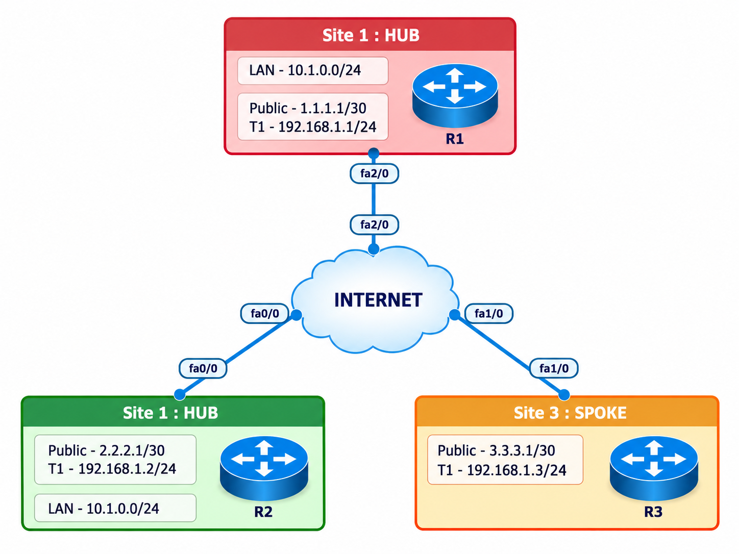
| Role | NBMA | Tunnel | LAN |
|---|---|---|---|
| R1 Hub | 198.51.100.1 | 172.16.123.1 | 10.1.1.0/24 |
| R2 Spoke | 198.51.100.2 | 172.16.123.2 | 10.2.2.0/24 |
| R3 Spoke | 198.51.100.3 | 172.16.123.3 | 10.3.3.0/24 |
Specific remote-spoke routes must remain visible. A hub summary or default makes the hub the routing next hop and prevents the normal Phase 2 direct-tunnel trigger.
2. Convert the Spokes to Multipoint GRE
Remove each fixed tunnel destination and enable mGRE. The static hub mapping and NHS remain because every spoke still registers with and queries the hub.
R1 Hub complete Tunnel0
interface Tunnel0
 ip address 172.16.123.1 255.255.255.0
 no ip redirects
 ip nhrp authentication DMVPN-LAB
 ip nhrp map multicast dynamic
 ip nhrp network-id 100
 tunnel source GigabitEthernet0/0
 tunnel mode gre multipoint
 tunnel protection ipsec profile DMVPN-PROFILE
 no shutdown
R2 Spoke complete Tunnel0
interface Tunnel0
 ip address 172.16.123.2 255.255.255.0
 no ip redirects
 ip nhrp authentication DMVPN-LAB
 ip nhrp map 172.16.123.1 198.51.100.1
 ip nhrp map multicast 198.51.100.1
 ip nhrp network-id 100
 ip nhrp nhs 172.16.123.1
 tunnel source GigabitEthernet0/0
 no tunnel destination
 tunnel mode gre multipoint
 tunnel protection ipsec profile DMVPN-PROFILE
 no shutdown
R3 Spoke complete Tunnel0
interface Tunnel0
 ip address 172.16.123.3 255.255.255.0
 no ip redirects
 ip nhrp authentication DMVPN-LAB
 ip nhrp map 172.16.123.1 198.51.100.1
 ip nhrp map multicast 198.51.100.1
 ip nhrp network-id 100
 ip nhrp nhs 172.16.123.1
 tunnel source GigabitEthernet0/0
 no tunnel destination
 tunnel mode gre multipoint
 tunnel protection ipsec profile DMVPN-PROFILE
 no shutdown
3. Preserve the Originating Spoke as the EIGRP Next Hop
The hub must advertise a spoke route back to other spokes without replacing the route's next hop with itself. This is the key routing difference from Phase 1.
R1 Hub
interface Tunnel0
 no ip split-horizon eigrp 100
 no ip next-hop-self eigrp 100
router eigrp 100
 eigrp router-id 1.1.1.1
 network 10.1.1.0 0.0.0.255
 network 172.16.123.0 0.0.0.255
 passive-interface Loopback0
 no auto-summary
R2 Spoke
router eigrp 100
 eigrp router-id 2.2.2.2
 network 10.2.2.0 0.0.0.255
 network 172.16.123.0 0.0.0.255
 passive-interface Loopback0
 no auto-summary
R3 Spoke
router eigrp 100
 eigrp router-id 3.3.3.3
 network 10.3.3.0 0.0.0.255
 network 172.16.123.0 0.0.0.255
 passive-interface Loopback0
no auto-summary10.3.3.0/24 should use 172.16.123.3 as next hop. If it points to 172.16.123.1, troubleshoot the hub's next-hop-self setting before testing NHRP.4. Keep the Same Dynamic IPsec Protection
The tunnel protection profile applies to hub-spoke and dynamically discovered spoke-spoke GRE peers. Use the same policy, key, transform set, and profile on all lab routers.
Common lab-only profile
crypto isakmp policy 10
 encr aes 256
 hash sha256
 authentication pre-share
 group 14
 lifetime 86400
crypto isakmp key DMVPN-LAB-ONLY address 0.0.0.0 0.0.0.0
crypto ipsec transform-set DMVPN-TS esp-aes 256 esp-sha256-hmac
 mode transport
crypto ipsec profile DMVPN-PROFILE
 set transform-set DMVPN-TS
After the first R2-to-R3 traffic, expect an additional spoke-to-spoke IKE/IPsec security association if the platform displays per-peer SAs.
5. Follow the Phase 2 Resolution Sequence
Route lookup
R2 selects R3's tunnel address as the next hop.
NHRP request
R2 asks the NHS for the NBMA mapping of 172.16.123.3.
Secure peer setup
R2 and R3 form dynamic GRE/IPsec state.
Direct forwarding
Subsequent packets bypass R1.
6. Verify the Direct Tunnel and Reproduce a Routing Failure
Capture the state before traffic, generate a sourced flow, then capture the new dynamic peer and direct path.
Before and after on R2
show clock
show ip route 10.3.3.0
show dmvpn
show ip nhrp
show crypto isakmp sa

ping 10.3.3.1 source 10.2.2.1 repeat 10
traceroute 10.3.3.1 source 10.2.2.1

show dmvpn
show ip nhrp
show crypto isakmp sa
show crypto ipsec sa
Expected proof
Route next hop: 172.16.123.3
NHRP peer: 172.16.123.3 -> 198.51.100.3
Traceroute: direct R2 -> R3
IPsec: counters increase for R3 peer
Break next-hop preservation
On R1, enter ip next-hop-self eigrp 100 under Tunnel0. Capture R2's route changing to the hub next hop and the loss of the normal direct-tunnel trigger. Restore no ip next-hop-self eigrp 100 and prove recovery.
7. Capture Genuine First-Hand Evidence
The completed GNS3 record shows the route and NHRP state before traffic, the dynamic spoke mapping after traffic, and the direct traceroute.
- Screenshot the topology and terminal clocks before traffic.
- Capture the remote-spoke route with its original spoke next hop.
- Capture DMVPN/NHRP/IPsec state before and after the first flow.
- Capture the forced next-hop-self failure and its effect on the path.
- Capture restored direct traceroute and increasing encryption counters.
8. Frequently Asked Questions
Why must Phase 2 spokes use mGRE?
A spoke must be able to send GRE traffic to both the hub and dynamically learned spoke NBMA addresses through one tunnel interface. A fixed tunnel destination cannot do that.
Why is no ip next-hop-self required on the hub?
It preserves the originating spoke tunnel address as the route next hop. That address is what the receiving spoke resolves through NHRP to create the direct tunnel.
Why should Phase 2 avoid a hub summary?
A hub summary points the spoke toward the hub rather than the remote spoke. Without the remote spoke's tunnel address as next hop, normal Phase 2 NHRP resolution does not create the optimized path.