DMVPN Phase 1: Build the Hub-and-Spoke Baseline
Configure one mGRE hub and two point-to-point GRE spokes. Register the spokes with NHRP, exchange routes with EIGRP, protect GRE with IPsec, and prove that spoke-to-spoke traffic stays on the hub path.
DMVPN Phase 1 at-a-Glance
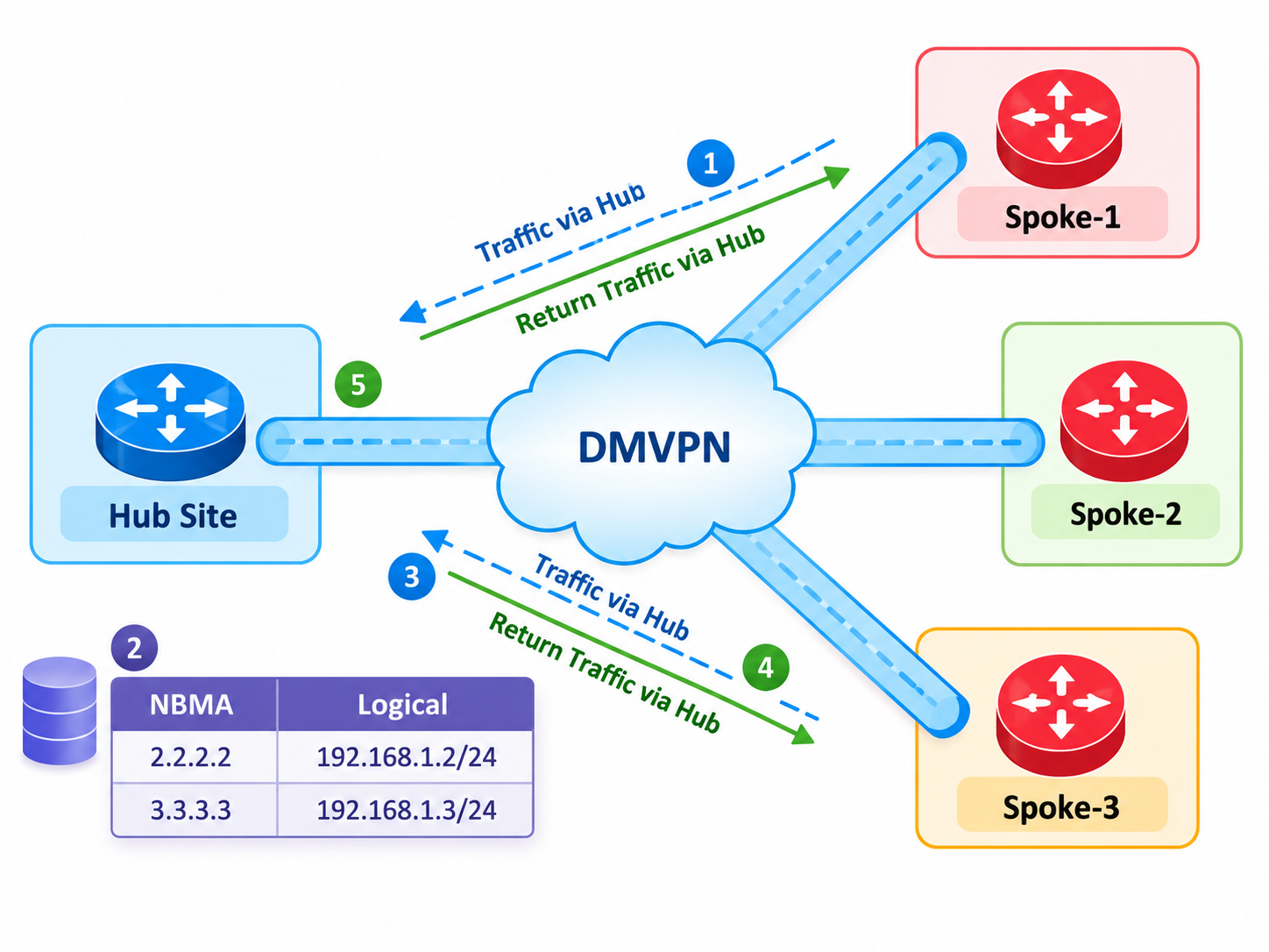
Phase 1 centralizes both control and forwarding. Spokes register with the NHRP server, but each spoke tunnel has only the hub as its GRE destination, so no direct spoke tunnel can form.
In This Lesson
1. Plan the Three-Router Topology
Use the documentation-only public range for the shared underlay. Loopbacks represent site LANs, and Tunnel0 is the enterprise overlay.
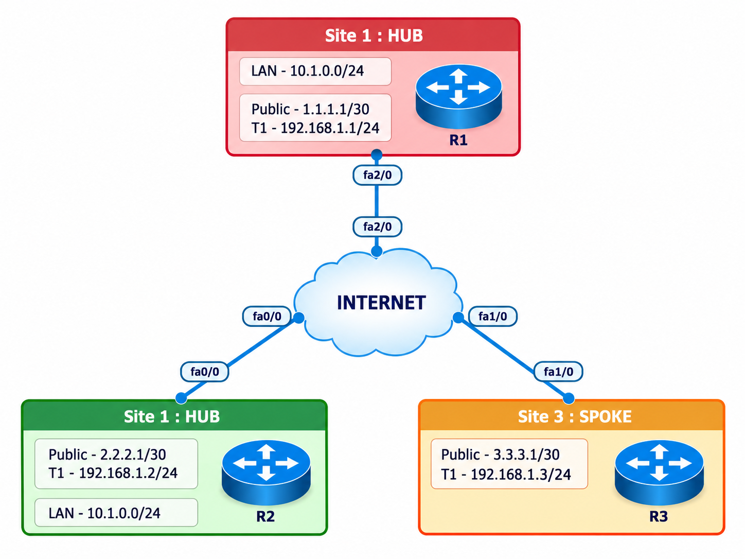
NBMA 198.51.100.1Tunnel 172.16.123.1LAN 10.1.1.0/24198.51.100.0/24Replace with your lab transport.2 and .3 NBMA.2 and .3 tunnel10.2.2.0/24 and 10.3.3.0/24| Router | Gi0/0 underlay | Tunnel0 | Loopback0 |
|---|---|---|---|
| R1 Hub | 198.51.100.1/24 | 172.16.123.1/24 | 10.1.1.1/24 |
| R2 Spoke | 198.51.100.2/24 | 172.16.123.2/24 | 10.2.2.1/24 |
| R3 Spoke | 198.51.100.3/24 | 172.16.123.3/24 | 10.3.3.1/24 |
2. Configure and Prove the Underlay
The NBMA addresses must already reach one another before GRE, NHRP, routing, or IPsec can work.
R1 Hub
interface GigabitEthernet0/0
 ip address 198.51.100.1 255.255.255.0
 no shutdown
interface Loopback0
 ip address 10.1.1.1 255.255.255.0
R2 Spoke
interface GigabitEthernet0/0
 ip address 198.51.100.2 255.255.255.0
 no shutdown
interface Loopback0
 ip address 10.2.2.1 255.255.255.0
R3 Spoke
interface GigabitEthernet0/0
 ip address 198.51.100.3 255.255.255.0
 no shutdown
interface Loopback0
 ip address 10.3.3.1 255.255.255.0
Underlay gate
show ip interface brief
R2# ping 198.51.100.1 source 198.51.100.2
R3# ping 198.51.100.1 source 198.51.100.3
3. Build the Phase 1 GRE and NHRP Overlay
The hub accepts dynamic NHRP registrations. Each spoke statically maps the hub tunnel address to its NBMA address and uses a fixed GRE destination.
R1 Hub
interface Tunnel0
 ip address 172.16.123.1 255.255.255.0
 no ip redirects
 ip nhrp authentication DMVPN-LAB
 ip nhrp map multicast dynamic
 ip nhrp network-id 100
 tunnel source GigabitEthernet0/0
 tunnel mode gre multipoint
 no shutdown
R2 Spoke
interface Tunnel0
 ip address 172.16.123.2 255.255.255.0
 no ip redirects
 ip nhrp authentication DMVPN-LAB
 ip nhrp map 172.16.123.1 198.51.100.1
 ip nhrp map multicast 198.51.100.1
 ip nhrp network-id 100
 ip nhrp nhs 172.16.123.1
 tunnel source GigabitEthernet0/0
 tunnel destination 198.51.100.1
 no shutdown
R3 Spoke
interface Tunnel0
 ip address 172.16.123.3 255.255.255.0
 no ip redirects
 ip nhrp authentication DMVPN-LAB
 ip nhrp map 172.16.123.1 198.51.100.1
 ip nhrp map multicast 198.51.100.1
 ip nhrp network-id 100
 ip nhrp nhs 172.16.123.1
 tunnel source GigabitEthernet0/0
 tunnel destination 198.51.100.1
no shutdownA Phase 1 spoke has only one GRE destination. Even when R2 learns R3's LAN, its tunnel can encapsulate traffic only toward R1. The hub decapsulates and re-encapsulates the packet for R3.
4. Run EIGRP Across the Overlay
Disable split horizon on the hub so it can advertise routes learned from one spoke back through the same multipoint tunnel. Keep normal next-hop-self behavior so spokes use the hub as their remote-route next hop.
R1
interface Tunnel0
 no ip split-horizon eigrp 100
router eigrp 100
 eigrp router-id 1.1.1.1
 network 10.1.1.0 0.0.0.255
 network 172.16.123.0 0.0.0.255
 passive-interface Loopback0
 no auto-summary
R2
router eigrp 100
 eigrp router-id 2.2.2.2
 network 10.2.2.0 0.0.0.255
 network 172.16.123.0 0.0.0.255
 passive-interface Loopback0
 no auto-summary
R3
router eigrp 100
 eigrp router-id 3.3.3.3
 network 10.3.3.0 0.0.0.255
 network 172.16.123.0 0.0.0.255
 passive-interface Loopback0
 no auto-summary
5. Protect GRE with an IPsec Profile
Apply the same lab-only IKEv1 and IPsec profile to all three routers. Confirm algorithm support on the actual IOS image, and never reuse the example secret in production.
R1, R2 and R3
crypto isakmp policy 10
 encr aes 256
 hash sha256
 authentication pre-share
 group 14
 lifetime 86400
crypto isakmp key DMVPN-LAB-ONLY address 0.0.0.0 0.0.0.0
crypto ipsec transform-set DMVPN-TS esp-aes 256 esp-sha256-hmac
 mode transport
crypto ipsec profile DMVPN-PROFILE
 set transform-set DMVPN-TS
interface Tunnel0
tunnel protection ipsec profile DMVPN-PROFILE6. Verify the Healthy State and Reproduce a Failure
Verify each layer in order. A ping alone does not prove that NHRP registration, routing, and encryption are correct.
Control-plane checks
show dmvpn
show ip nhrp
show ip eigrp neighbors
show ip route eigrp
show crypto isakmp sa
show crypto ipsec sa
Forwarding proof from R2
ping 10.3.3.1 source 10.2.2.1
traceroute 10.3.3.1 source 10.2.2.1
show ip route 10.3.3.0

Expected path: R2 -> R1 -> R3
Introduce one controlled NHRP failure
Change R3's NHRP authentication string to WRONG-LAB. Record the loss of registration and routes, restore DMVPN-LAB, then prove recovery without changing unrelated settings.
| Symptom | Likely layer | First evidence |
|---|---|---|
| Tunnel down/down | Source or destination missing | show interface tunnel0 |
| Tunnel up, no registration | NHRP authentication, NHS, or map | show ip nhrp detail |
| Registration exists, no routes | EIGRP or multicast mapping | show ip eigrp neighbors |
| Routes exist, no encrypted traffic | IKE/IPsec mismatch | SA state and encaps/decaps counters |
7. Capture Genuine First-Hand Evidence
The completed GNS3 overlay run is available as a timestamped text record. The remaining checklist preserves the evidence still required for IPsec and fault injection.
- Capture the full topology with R1, R2, and R3 labels visible.
- Save
show clock,show version, sanitized running tunnel/EIGRP/crypto configuration, NHRP, DMVPN, route, and SA output. - Capture the intentional authentication failure before correction.
- Capture the restored registration, route, IPsec counters, ping, and hub-in-path traceroute.
- Redact secrets only; retain device names, timestamps, software versions, and meaningful counters.
8. Frequently Asked Questions
Why do Phase 1 spokes use tunnel destination?
They use ordinary point-to-point GRE. A fixed destination limits each spoke tunnel to the hub and prevents direct spoke-to-spoke tunnel creation.
Why disable EIGRP split horizon only on the hub?
The hub learns spoke routes on Tunnel0 and must advertise them back out Tunnel0 to other spokes. Split horizon blocks that reflection unless disabled.
What proves Phase 1 behavior?
R2 can reach R3's LAN, but the route next hop is the hub and a sourced traceroute includes R1. No dynamic R2-to-R3 NHRP peer should appear.